Why Monoblock LNB Position Matters More Than Size
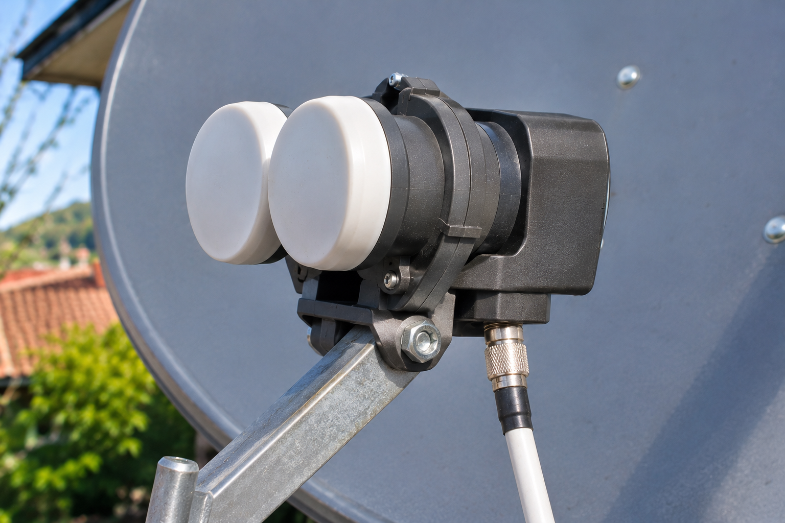
You upgrade to a larger satellite dish, expecting better reception from Astra 19.2°E and Hot Bird 13°E. Instead, one satellite improves while the other becomes weaker. The reflector is bigger, the monoblock is new, and the receiver settings appear correct. So why doesn’t the larger antenna deliver better reception from both positions?
A monoblock LNB depends on precise feed geometry. Its two receiving feeds must correspond to the directions in which the reflector focuses signals from two different satellites. If the feed spacing, focal ratio, mounting depth, or orientation does not suit the antenna, additional reflector area may not produce the expected improvement. Before replacing a dish or buying a different LNB, verify that the monoblock is physically compatible with the reflector and positioned correctly.
A six-degree-class monoblock is commonly used to receive Astra 19.2°E and Hot Bird 13°E through one compatible offset dish. The orbital positions differ by approximately 6.2 degrees in longitude, but their apparent angular separation depends on the receiving location. A monoblock has fixed feed spacing designed around particular antenna characteristics. Dish size provides potential gain, while feed geometry determines how effectively that gain is used for both satellite directions.
Why Monoblock Position Can Matter More Than Dish Size
A larger reflector generally offers more potential antenna gain than a smaller reflector operating at the same frequency and efficiency.
However, that potential gain is not automatically available to every receiving feed installed in front of the dish.
For reliable dual-satellite reception, the monoblock must place its receiving feeds at positions suited to the reflector’s geometry.
If the physical arrangement is incorrect, one satellite may receive substantially less effective gain than expected.
Two Satellites Require Two Receiving Positions
A conventional single-satellite installation uses one feed assembly to collect energy focused by the reflector.
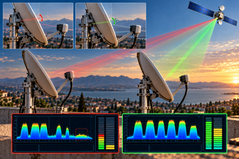
Signals from a second satellite arrive from a different direction and are focused toward a different region.
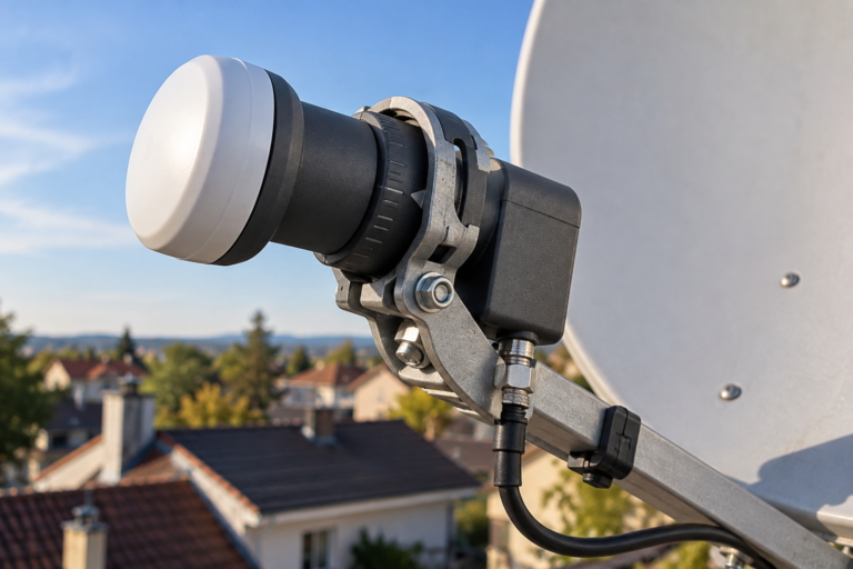
A monoblock accommodates this by incorporating two feed assemblies in a common housing.
Each feed is intended to collect the corresponding satellite signal.
The required feed positions depend on the antenna’s optical characteristics and the apparent directions of the satellites.
Why Bigger Does Not Automatically Mean Better
Increasing reflector diameter can improve theoretical receiving gain, but only when the associated feed system uses that reflector effectively.
An incompatible monoblock may introduce off-axis losses or inappropriate reflector illumination.
Consequently, a larger antenna combined with poor feed geometry can perform worse than a smaller, correctly matched installation on a particular satellite path.
This does not make diameter irrelevant. It means antenna gain and feed geometry must be evaluated together.
How an Offset Satellite Dish Forms Its Receiving Geometry
An offset satellite dish is a section of a larger paraboloidal reflecting surface.
The feed is positioned to collect energy reflected from the dish’s intended receiving direction.
This arrangement allows the feed assembly to avoid obstructing a substantial part of the reflector’s effective aperture.
The Main Receiving Direction
When the reflector is correctly aligned for its intended satellite, the corresponding incoming wavefront is concentrated toward the feed region.
The exact feed position and illumination pattern are determined by the reflector’s design.
An incorrectly positioned feed may collect less energy or illuminate the reflector inefficiently.
Receiving a Second Satellite Off-Axis
For an incoming signal from a nearby orbital position, the reflected field is displaced relative to the primary feed.
The secondary feed must be placed where sufficient usable energy can be collected.
Off-axis performance is influenced by reflector geometry, feed positioning, and aberrations.
A monoblock designed for the correct reflector can provide reliable reception on both paths, but its fixed mechanical arrangement limits the available adjustments.
Why Feed Phase Center Matters
The physical front surface of an LNB is not necessarily the exact electromagnetic reference point of its receiving feed.
The effective phase center depends on feed design and operating conditions.
Two LNBs with similar external dimensions may therefore interact differently with the same reflector.
This is one reason that mounting a replacement monoblock at an apparently identical depth does not always reproduce the previous reception quality.
What Monoblock Feed Spacing Actually Controls
The distance between the two feed assemblies is a defining characteristic of a monoblock.
Unlike two separate LNBs on an adjustable holder, the spacing of an ordinary integrated monoblock is fixed by its construction.
Orbital Separation Is Not Physical Feed Separation
Astra 19.2°E and Hot Bird 13°E are separated by 6.2 degrees in orbital longitude.
That numerical difference does not directly specify the physical distance between the feedhorns.
The apparent angular separation in the receiving sky depends on geographic location.
The conversion from arrival-angle difference to feed displacement also depends on the reflector’s focal geometry.
Why the Same Monoblock Does Not Fit Every Reflector
A reflector with a different focal length generally requires a different lateral displacement to accommodate a particular angular separation.
In a simplified small-angle model, lateral feed displacement is approximately proportional to effective focal length.
Real offset reflectors require more detailed consideration of optical geometry and off-axis behavior.
Nevertheless, the principle explains why fixed feed spacing cannot be assumed suitable for every dish.
What Happens When Spacing Is Incorrect
One feed may remain close to its intended receiving position while the other operates away from its optimum.
The secondary path can then lose usable gain or polarization performance.
Some carriers may continue locking while others become unstable.
A sufficiently severe mismatch can prevent the secondary satellite from being received reliably at all.
A monoblock described as a six-degree model is designed for a particular class of dual-satellite installations. The description does not mean the two feedhorns are mechanically separated by six degrees or that the unit will work equally well with every reflector.
Why F/D Ratio Is Critical for Monoblock Compatibility
The focal-length-to-diameter ratio, written F/D, describes a fundamental geometric relationship in a satellite reflector.
It helps characterize the antenna’s focal geometry and the feed design needed for efficient illumination.
F/D = Focal Length / Reflector Diameter
For a conventional circular parent paraboloid, the relationship describes the focal length relative to aperture diameter. Offset reflectors are sections of a parent paraboloid, and manufacturers may specify geometry using their own reference definitions.
When assessing compatibility, use the reflector and monoblock manufacturers’ stated specifications rather than estimating focal geometry from external appearance alone.
Two 80cm Dishes May Have Different Geometry
Nominal diameter alone does not fully describe a reflector.
Different antennas can have different focal lengths, offset angles, aperture efficiencies, and feed-support arrangements.
A monoblock that performs correctly on one reflector may therefore operate differently on another of similar nominal size.
A Real Manufacturer Example
Inverto offers a six-degree monoblock model intended for Astra 19.2°E and Hot Bird 13°E reception using an 80cm offset reflector with F/D = 0.6.
This is a specific product requirement, not a universal specification for all 80cm dishes or six-degree monoblocks.
It demonstrates that the manufacturer considers reflector geometry part of the receiving system’s compatibility.
Why an F/D Mismatch Matters
If the reflector geometry differs significantly from the monoblock’s intended design, the feed positions may no longer correspond appropriately to the required satellite directions.
Feed illumination may also become less efficient.
As a result, increasing antenna size without correcting compatibility may fail to provide the expected reception improvement.
Why Monoblock Mounting Depth Affects Reception
Feed spacing is not the only relevant mechanical dimension.
The position of the monoblock along the feed arm can also influence how its receiving assemblies interact with the reflector.
Forward and Backward Positioning
Moving a feed assembly along its mounting axis changes its relationship to the reflector’s intended focal region.
This can alter illumination and receiving efficiency.
The actual effect depends on the antenna and feed design.
A small movement may be significant in a marginal installation but negligible in another.
Why Identical Collar Position Is Not Always Enough
Different monoblock models may have different feedhorn shapes, housing dimensions, and effective phase-center locations.
Therefore, using the same visible collar reference does not guarantee that both products deliver identical RF performance.
A replacement should initially be installed according to its manufacturer’s instructions.
Avoid Random Mounting Adjustments
Moving the monoblock backward or forward without measurement can reduce reception quality.
Where the mounting design permits adjustment, use controlled changes while checking representative carriers from both satellites.
Do not assume that the position giving the highest signal-strength percentage on one transponder is optimal for the entire installation.
Monoblock Tilt, Rotation and Polarization Skew
A monoblock’s physical orientation affects the relative positions of its two feeds.
It may also affect how the feeds are aligned with incoming linearly polarized signals.
These effects should be evaluated separately even when one physical adjustment influences both.
Why Feed Tilt Matters
The apparent directions of Astra and Hot Bird are not necessarily aligned with the horizontal axis of the monoblock housing at every receiving location.
The appropriate relative feed orientation depends on satellite geometry and the antenna arrangement.
Manufacturer installation diagrams provide the intended starting configuration.
Why Polarization Skew Matters
Linear satellite transmissions require appropriate polarization alignment to minimize unwanted reception from the orthogonal polarization.
Incorrect skew can degrade polarization isolation and contribute to interference.
Some transponders may be more noticeably affected than others because of differences in their available reception margins.
Why Left and Right Instructions Can Be Misleading
An installer looking at the dish from the front sees the feed positions in the opposite left-right arrangement from someone standing behind it.
Therefore, an instruction that simply says to place one feed on the left may be ambiguous.
Use the manufacturer’s specified viewing direction and installation diagram.
Do not rely on generic internet illustrations that may describe a different monoblock design.
Why a Larger Dish Can Make Incorrect Monoblock Positioning More Noticeable
At the same frequency and comparable efficiency, a larger reflector generally offers higher receiving gain.
However, its directional main beam also generally becomes narrower.
This means positioning accuracy becomes increasingly important as aperture size grows.
The Gain Advantage
For equal aperture efficiency at the same frequency, the theoretical gain difference between two circular apertures is:
Gain Difference = 20 × log10(D2 / D1)
For an illustrative change from 60cm to 80cm:
20 × log10(80 / 60) ≈ 2.50 dB.
This calculation describes a theoretical aperture-gain difference, not a guaranteed installed improvement.
Why Off-Axis Positioning Can Offset the Gain
If the secondary feed is positioned incorrectly, the receiving gain available to that satellite may be reduced.
The additional gain expected from a larger reflector may therefore be partly or substantially lost.
The amount depends on the specific mismatch and cannot be determined from nominal dish size alone.
Size Still Matters for Weak Coverage
If the feed geometry is correct but the available satellite link margin is insufficient, a larger compatible antenna may be appropriate.
Local EIRP, carrier requirements, rain availability, and antenna efficiency influence that decision.
Our related guide, Why Hot Bird Needs Different Dish Sizes in Europe, explains how geographic coverage and link-budget requirements influence reflector selection.
The two decisions are connected but distinct: selecting enough antenna gain and positioning the feed correctly to use that gain.
How to Verify Monoblock Compatibility Before Buying
Before purchasing a monoblock or replacing a reflector, check the complete receiving arrangement.
1. Confirm the Intended Satellite Pair
Identify the actual orbital positions the unit is designed to receive.
For a typical European six-degree installation, these may be Astra 19.2°E and Hot Bird 13°E.
Do not assume that every monoblock described as a dual-satellite model is designed for that pair.
2. Check Recommended Dish Size
Read the manufacturer’s supported or recommended reflector size.
The stated diameter should be considered alongside the antenna geometry and installation requirements.
3. Verify F/D Compatibility
Where the manufacturer specifies a focal ratio, compare it with the reflector’s documented geometry.
Do not assume that all dishes with the same nominal diameter have identical focal ratios.
4. Check Mounting Collar Dimensions
Verify that the monoblock fits the feed holder correctly.
Some products use mounting adapters, but physical fit alone does not prove optical compatibility.
5. Confirm Switching and Receiver Support
Check the monoblock’s DiSEqC requirements and satellite-to-port assignments.
Also verify its output architecture and compatibility with the intended receiver or distribution system.
Wrong satellite selection can prevent reception even when the feed geometry is correct.
6. Review the Installation Instructions
Use the exact product’s mounting and orientation instructions.
Where a manufacturer provides a recommended alignment reference, follow it rather than assuming that either orbital position must always be the primary feed.
How to Optimize an Existing Monoblock Installation
If one satellite works while the other remains weak, begin with evidence before replacing hardware.
Step 1: Verify Both Satellite Identities
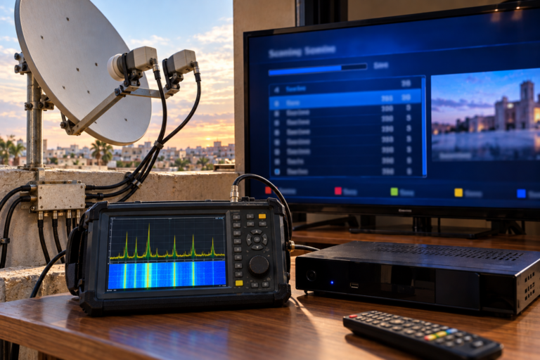
Use currently verified reference carriers and suitable service information to confirm that the receiver selects the intended satellite through each monoblock path.
Do not rely on satellite labels or raw strength percentages alone.
Step 2: Record Initial Reception Quality
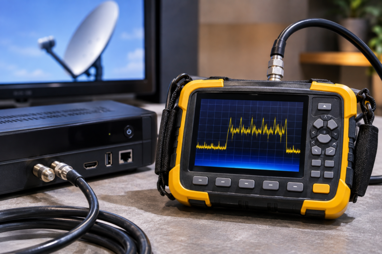
Measure representative transponders from both orbital positions.
Where supported, record lock status, carrier-to-noise ratio, modulation error ratio, and applicable error measurements.
Use the same analyzer and comparable conditions for repeatable testing.
Step 3: Confirm the Hardware Match
Check monoblock model, recommended dish diameter, focal ratio, mounting collar, and intended orbital separation.
If the hardware is fundamentally incompatible, alignment adjustments alone may not produce reliable reception on both satellites.
Step 4: Inspect Mounting and Orientation
Check whether the feed assembly is properly seated and supported.
Verify mounting depth and orientation according to the manufacturer’s guidance.
Look for loose clamps, damaged brackets, or unintended movement.
Step 5: Optimize the Weakest Required Carriers
A qualified installer can evaluate controlled adjustments while monitoring both satellite paths.
For each selected carrier, consider its reception margin relative to its transmission requirements rather than comparing arbitrary receiver percentages.
An adjustment that improves one satellite but causes unacceptable degradation on the other is not an overall improvement.
Step 6: Secure and Recheck
Secure the installation according to the manufacturer’s mechanical specifications.
Repeat measurements after tightening because mechanical stress can slightly change feed or reflector position.
Document the final configuration for future troubleshooting.
Confirm satellite identities → Verify hardware compatibility → Measure both receiving paths → Check mounting geometry → Optimize positioning → Secure equipment → Repeat measurements.
Do not use a channel scan or factory reset as a substitute for correcting a genuine feed-position problem.
When Two Separate LNBs May Be Better Than a Monoblock
An integrated monoblock offers convenience because it combines two feed assemblies and switching functions in one housing.
However, fixed feed spacing limits mechanical flexibility.
Advantages of Adjustable Multi-Feed Systems
Two separate LNBs mounted on a suitable adjustable holder may allow greater control over lateral feed position, mounting depth, and orientation.
This flexibility can be valuable when the reflector geometry is unsuitable for a fixed monoblock.
It may also help accommodate installation-specific receiving conditions.
Separate LNBs Are Not Automatically Better
The multi-feed holder must still be compatible with the dish.
Off-axis feed performance remains subject to reflector limitations.
The system also needs suitable switching hardware and receiver configuration.
A properly matched monoblock may be simpler and entirely adequate for the required satellite pair.
When a Different Reflector Is Justified
If both receiving paths are correctly configured but cannot achieve sufficient reception margin, antenna size or reflector design may need reconsideration.
The decision should account for satellite coverage, required services, weather margin, mechanical stability, and feed compatibility.
Replacing the dish without evaluating these factors may reproduce the problem.
What Different Monoblock Reception Patterns Reveal
| Observed Pattern | Possible Explanation | First Useful Check |
|---|---|---|
| One satellite is strong, the other consistently weak | Feed-position mismatch, coverage difference, or pointing imbalance | Verify feed geometry and measured margins |
| Both satellites are weak | General pointing, hardware, or system-loss problem | Confirm alignment and the common RF path |
| One satellite has no carrier lock at all | Incorrect selection, severe geometry mismatch, or path fault | Verify DiSEqC mapping and reference carriers |
| Performance worsens after increasing dish size | Potential incompatibility between monoblock spacing and reflector geometry | Compare recommended dish size and F/D |
| Reception changes when the monoblock is rotated | Feed positioning or polarization-alignment sensitivity | Check multiple carriers on both satellites |
| Reception changes after tightening the mounting clamp | Mechanical movement or mounting-depth variation | Inspect mounting stability and repeat measurements |
| Only certain transponders fail | Carrier-specific reception margin or frequency-dependent impairment | Compare verified carrier parameters and quality |
| Wrong satellite appears in receiver menu | Satellite-to-port mapping or database configuration | Confirm the actual selected feed |
The patterns above help prioritize troubleshooting but do not independently prove a specific hardware or installation defect.
Reality Check: Position Matters, but Size Is Still Part of the Link Budget
The title does not mean that reflector diameter is unimportant.
Dish size influences potential antenna gain, beamwidth, and available reception margin.
Feed spacing, focal geometry, mounting depth, and orientation determine how effectively that antenna can receive the intended satellite directions.
A correctly positioned monoblock on an undersized dish may still lack sufficient margin. A larger dish with incompatible feed geometry may also perform poorly.
Reliable dual-satellite reception requires both appropriate antenna gain and correctly matched feed positioning.
Final Verdict
Monoblock LNB positioning can matter more than increasing dish size when the existing installation suffers from incorrect feed geometry.
The two feeds must be positioned appropriately for the reflector’s focal characteristics and the apparent directions of the intended satellites.
Fixed feed spacing, reflector F/D ratio, mounting depth, and tilt all influence the receiving performance of Astra 19.2°E and Hot Bird 13°E.
A larger reflector can provide more potential gain, but that advantage may be reduced when the monoblock is incompatible with its optical geometry.
Before upgrading the dish, confirm the monoblock’s specifications, verify the physical installation, and measure representative carriers from both satellites.
The best solution is not automatically the largest reflector. It is a compatible, accurately aligned receiving system with sufficient margin for the services it is intended to deliver.
Frequently Asked Questions
Why does monoblock LNB position affect satellite reception?
Each monoblock feed must collect energy focused by the reflector from a different satellite direction. Incorrect positioning can reduce receiving gain or polarization performance, causing weak or missing carriers.
Can I use a six-degree monoblock with any satellite dish?
No. Monoblocks are designed around particular reflector geometries and satellite separations. Check the manufacturer’s supported dish size, F/D ratio, mounting requirements, and intended satellite pair.
What does F/D mean in a monoblock installation?
F/D expresses the relationship between reflector focal length and diameter. It helps describe the antenna’s focal geometry, which influences feed compatibility and positioning.
Can mounting depth affect Astra and Hot Bird reception?
Yes. Changing the feed’s distance from the reflector can affect illumination and receiving efficiency. The significance depends on the reflector and feed design, so adjustments should be controlled and measured.
Is a bigger dish always better with a monoblock?
No. A larger reflector can offer additional antenna gain, but it may also require more precise pointing and compatible feed geometry. An unsuitable monoblock can prevent the expected improvement.
Can rotating a monoblock improve the weaker satellite?
Controlled rotation may improve relative feed positioning or polarization alignment, depending on the model. However, incorrect rotation can degrade the other satellite. Follow manufacturer instructions and evaluate both paths.
Why does one satellite disappear after changing dish size?
The new reflector may have different focal geometry that does not match the monoblock’s fixed feed spacing. Switching configuration, pointing, and other installation changes should also be checked before reaching a conclusion.
Are two separate LNBs better than a monoblock?
Separate LNBs with a compatible adjustable holder can provide greater flexibility in feed positioning. They may be preferable for unusual reflector geometries, but they still require correct alignment and appropriate switching hardware.