Why Hot Bird Signal Changes Between H and V
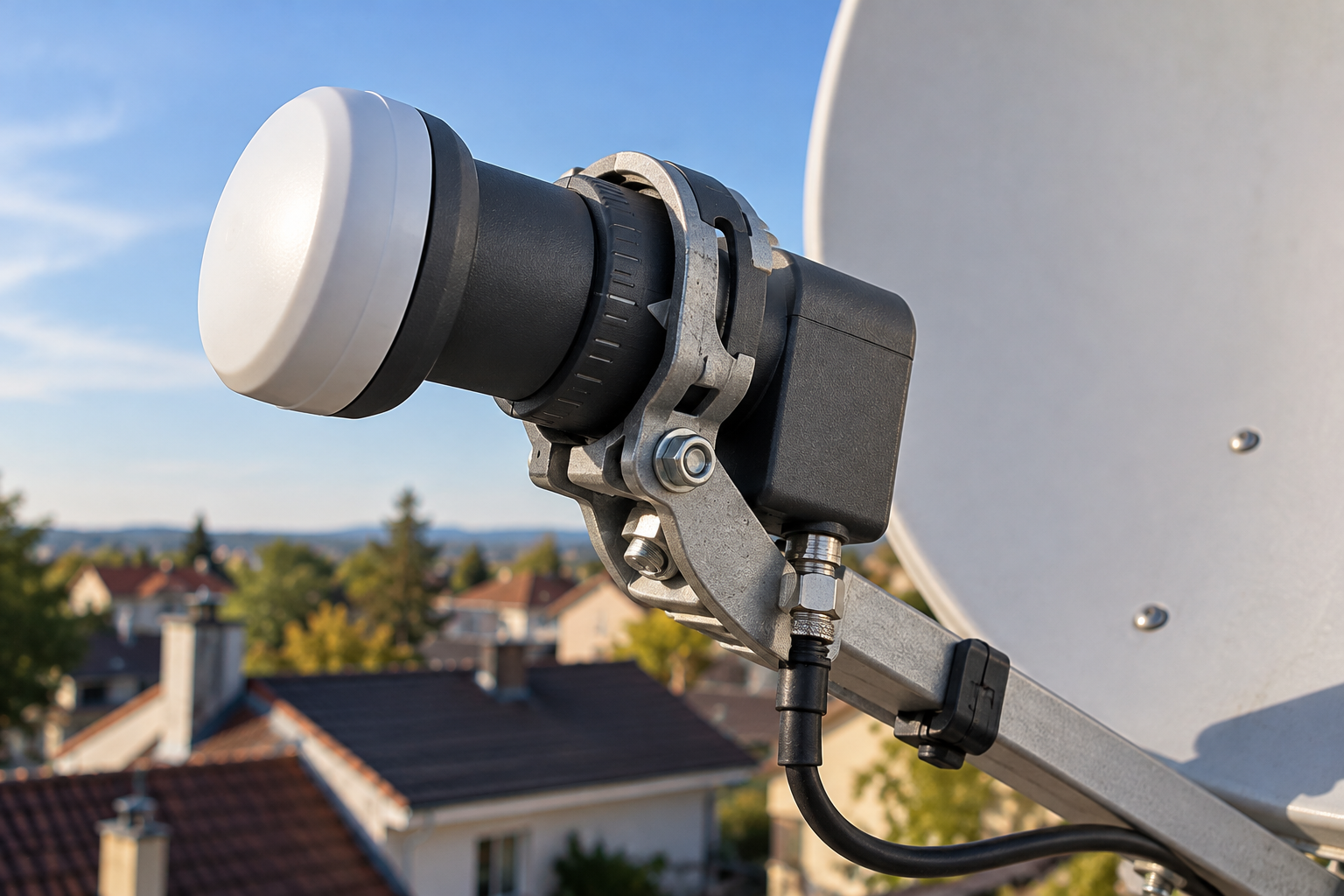
Your Hot Bird 13°E receiver locks onto horizontal transponders without trouble, but vertical frequencies appear weaker, unstable, or completely missing. On another installation, the situation may be reversed: vertical channels work normally while horizontal transponders refuse to lock. The dish is receiving the satellite, so why does changing from H to V make such a difference?
The pattern often points toward polarization selection, but it does not automatically mean the LNB is defective. A conventional universal LNB relies on control voltage to select horizontal or vertical reception, while signal quality also depends on feed alignment, polarization isolation, and the available margin of individual transponders. The first diagnostic step is to determine whether one polarization is being selected incorrectly or whether both are available but one has poorer reception quality.
Hot Bird 13°E uses linearly polarized Ku-band transmissions. In a conventional universal-LNB installation, nominal 13V and 18V control states select vertical and horizontal polarization, respectively. The receiver also uses 22 kHz signaling for low/high band selection. These control methods should not be confused with the different distribution procedures used in Quattro, multiswitch, and Unicable/SCR systems.
What Horizontal and Vertical Polarization Mean on Hot Bird
Satellite transmissions use polarization to describe the orientation of the electromagnetic field carried by a radio signal.
For linearly polarized Ku-band services, horizontal and vertical polarization provide two orthogonal orientations that help satellite operators reuse frequency resources efficiently.
A receiving LNB must select and process the intended polarization with sufficient isolation from unwanted energy on the orthogonal polarization.
This distinction matters because two transponders can occupy the same nominal frequency region while using different polarizations.
However, H and V are not separate satellites, and one polarization is not inherently stronger than the other.
Actual reception depends on the transmitted carrier, beam characteristics, receiving equipment, and local installation conditions.
Why One Working H Transponder Does Not Prove V Is Healthy
A receiver that successfully locks a horizontal carrier demonstrates that the selected RF path can receive that particular transmission.
It does not prove that the receiver can select vertical polarization correctly.
Similarly, receiving one vertical transponder does not establish that every horizontal carrier has adequate reception margin.
Effective troubleshooting therefore requires comparing several currently valid transponders on both polarizations.
How a Universal LNB Selects H and V
In a conventional universal-LNB system, the satellite receiver supplies DC power and control signals through the coaxial cable.
For polarization selection, the LNB interprets nominal voltage states rather than a separate software-only H/V command.
| Control State | Typical Selection | Purpose |
|---|---|---|
| Approximately 13V, no 22 kHz tone | Vertical Low | V polarization, lower band |
| Approximately 18V, no 22 kHz tone | Horizontal Low | H polarization, lower band |
| Approximately 13V with 22 kHz tone | Vertical High | V polarization, upper band |
| Approximately 18V with 22 kHz tone | Horizontal High | H polarization, upper band |
These are conventional nominal control states. Actual operating tolerances and thresholds depend on the equipment manufacturer’s specifications.
The LNB receives the requested selection and converts the corresponding satellite band into the receiver’s intermediate-frequency range.
Why 22 kHz Is Not the Polarization Switch
A frequent configuration mistake is treating 22 kHz signaling as the mechanism that selects horizontal or vertical polarization.
In a conventional universal LNB, voltage selects polarization while the 22 kHz tone selects the frequency band.
Both control mechanisms work together, but they perform different functions.
A failure affecting upper-band carriers can therefore resemble a polarization fault if the user compares transponders without accounting for their band assignments.
If every horizontal carrier fails while vertical carriers remain available in both bands, investigate polarization selection. If only one frequency band fails across both polarizations, band switching becomes a more relevant suspect.
Why Horizontal Hot Bird Channels Work but Vertical Channels Fail
When horizontal transponders work consistently but vertical transponders fail, the cause may lie in the switching electronics, receiver configuration, or distribution path.
One possibility is that the system remains in the horizontal selection state when the receiver requests vertical reception.
However, a functioning horizontal path does not prove that the receiver’s voltage is always correct.
The relevant question is whether the proper voltage state reaches the LNB when each verified transponder is selected.
Incorrect LNB Configuration
Some receivers support multiple LNB types, local oscillator settings, and control methods.
If the wrong configuration is selected, the tuner may request an inappropriate signal path.
Before changing the dish or rotating the LNB, verify that the receiver configuration matches the actual installed hardware.
This is especially important with multi-satellite installations using DiSEqC switching.
An incorrect switch assignment may connect the tuner to another feed, creating misleading results that appear to involve polarization.
For more detail on how receiver settings and incorrect satellite selection can confuse scanning and tuning, see Why Your Receiver Finds the Wrong Astra Channels. Although that guide focuses on Astra, the same need to verify the selected RF path applies to Hot Bird installations.
Faulty LNB Switching Electronics
An LNB with damaged or unstable internal switching circuitry may fail to select the requested polarization reliably.
The problem may affect every transponder in one polarization or appear intermittently.
However, that diagnosis should follow proper tests of receiver output voltage, cable condition, and connected switching equipment.
Why Vertical Channels Work but Horizontal Channels Fail
When vertical transponders remain stable while horizontal reception disappears, the higher-voltage selection state deserves particular attention.
In a conventional system, the receiver must provide an appropriate voltage at the LNB input for horizontal selection.
If excessive resistance or another electrical fault prevents the required state from reaching the LNB, horizontal reception may fail.
Voltage Drop Along the Coaxial Path
Long cable runs, deteriorated connectors, damaged conductors, and unsuitable distribution components can affect DC voltage delivery.
The significance depends on the receiver’s supply capability, cable resistance, LNB current consumption, and switching thresholds.
It is not correct to assume that every long coaxial cable causes horizontal polarization failure.
A sound cable installation should be evaluated against the actual electrical requirements of the equipment.
Receiver Power Supply Limitations
A receiver with a defective or overloaded LNB power output may fail to supply the required control voltage under operating load.
Testing the voltage without the LNB connected may not reveal the same behavior that occurs when the system is powered normally.
Appropriate measurements under load can therefore be more informative, provided the equipment and test procedures support them.
Do not attempt improvised voltage injection or connect external power supplies to a satellite input without a compatible, documented arrangement.
When Both H and V Work but Signal Quality Is Different
Not every H/V imbalance is an electrical switching failure.
Sometimes both polarizations lock successfully, yet one set of transponders shows consistently lower MER or less reliable reception.
This can result from antenna alignment, feed orientation, unequal carrier margins, interference, or equipment performance.
Different Transponder Reception Margins
Hot Bird 13°E is an orbital position served by multiple satellite resources and numerous transponders.
Individual carriers need not have identical received power, modulation characteristics, or required decoding margin.
Consequently, comparing one H carrier with one V carrier does not necessarily provide a valid measurement of polarization-system performance.
A more useful comparison examines multiple carriers, their transmission parameters, and their performance relative to the appropriate decoding requirements.
Reception Near a Coverage Boundary
In locations with limited available downlink margin, comparatively small differences in receiver performance can affect which transponders remain usable.
The relevant factors include antenna gain, local beam coverage, atmospheric attenuation, and the receiving system’s overall noise performance.
Our related guide, Why Astra Reception Changes Near a Footprint Edge, examines how beam coverage and reduced link margin affect reception near the edge of an intended service area. The same link-budget principles can help explain why some Hot Bird transponders become marginal before others.
However, a coverage limitation should not be mistaken for a failed 13/18V switch. The two problems require different remedies.
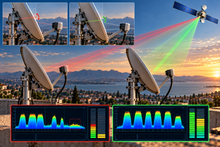
How LNB Skew and Cross-Polarization Affect H and V
The physical rotation of the receiving feed helps align its polarization axes with the incoming linearly polarized signals.
This adjustment is commonly called LNB skew.
Correct skew depends on the orbital geometry, receiving location, antenna arrangement, and equipment design.
What Happens When the LNB Is Rotated Incorrectly?
Incorrect feed rotation can reduce polarization discrimination, allowing more unwanted energy from the orthogonal polarization into the selected signal path.
This is generally described in terms of cross-polarization isolation.
The practical consequences depend on the strengths and spectral relationships of the desired and interfering signals.
Some transponders may remain stable while others lose usable MER.
Why Skew Cannot Fix Every H/V Problem
Rotating the LNB changes physical polarization alignment. It does not repair an electrical control circuit that cannot select the requested polarization.
If an entire polarization is missing because of faulty switching, adjusting skew may only disturb an otherwise correctly aligned antenna system.
Determine whether both polarization states can be selected before making significant mechanical adjustments.
How Cable and Connector Faults Affect Polarization Switching
The coaxial cable in a conventional satellite installation carries both the converted RF signal and the LNB’s DC power and control information.
Damage can therefore affect reception in more than one way.
RF attenuation and impedance mismatch can reduce signal quality, while excessive DC resistance or unstable contacts can interfere with LNB operation and control.
These effects should be diagnosed separately.
Why One Receiver May Behave Differently
In a Twin or Quad LNB installation, separate outputs can feed different receivers through independent cables.
If one television receives both H and V while another consistently loses horizontal transponders, the difference may lie in a cable, connector, receiver, output, or configuration.
The shared dish alone does not establish that every connected RF path is healthy.
Controlled comparisons using known-good equipment can help determine whether the failure follows the receiver, cable, or LNB output.
Disconnect the relevant receiver and powered distribution equipment before changing coaxial connections. Avoid shorting the cable’s center conductor to its shield. Voltage measurements should be made using equipment designed for powered satellite coaxial systems and the manufacturer’s recommended procedure.
Why Multiswitch and Unicable Systems Need Different Diagnostics
The familiar 13/18V selection model describes a conventional universal LNB connected through a compatible switching path.
It should not be applied without modification to every satellite distribution installation.
Quattro LNB and Multiswitch Systems
A Quattro LNB provides four fixed outputs representing the low/high frequency bands and vertical/horizontal polarization combinations.
A compatible multiswitch routes the required input to the connected receiver or tuner.
If one multiswitch input, cable, or routing component fails, an entire group of transponders may become unavailable.
The fault could be mistakenly attributed to poor polarization reception at the dish.
Unicable, SCR and dCSS Installations
Single-cable satellite distribution systems use supported control commands and assigned user bands to deliver selected transponders to compatible tuners.
In these systems, a conventional receiver-side voltage change alone does not perform the same direct H/V selection function as it does with a standard universal LNB.
Incorrect user-band configuration, command compatibility, or routing can create missing-transponder patterns.
Testing should follow the specifications of the installed SCR or dCSS equipment rather than treating the system as a direct universal-LNB connection.
What Different H/V Failure Patterns Reveal
The most useful evidence is often the relationship between the affected transponders.
| Observed Pattern | Possible Cause | First Diagnostic Check |
|---|---|---|
| Horizontal fails across both bands, vertical works | 18V selection, power delivery, LNB or distribution fault | Verify H selection and voltage path |
| Vertical fails across both bands, horizontal works | 13V selection, LNB switching or routing problem | Verify V selection and configuration |
| Both polarizations fail in the high band | Band-selection or distribution issue | Check applicable 22 kHz signaling and high-band path |
| Both H and V lock, but selected carriers have low MER | Alignment, interference, or limited reception margin | Compare multiple verified carriers and skew |
| One receiver loses H while another works | Local cable, tuner, LNB output or settings | Compare equivalent receiver paths |
| One band/polarization group fails on a multiswitch | Fixed-input connection or multiswitch routing fault | Inspect the relevant distribution input and route |
| Fault appears after changing receiver settings | Incorrect LNB type, switching or user-band configuration | Restore and verify the appropriate configuration |
These symptoms are diagnostic clues, not definitive proof. A reliable conclusion requires confirming the relevant transponder parameters and observing the actual signal path.
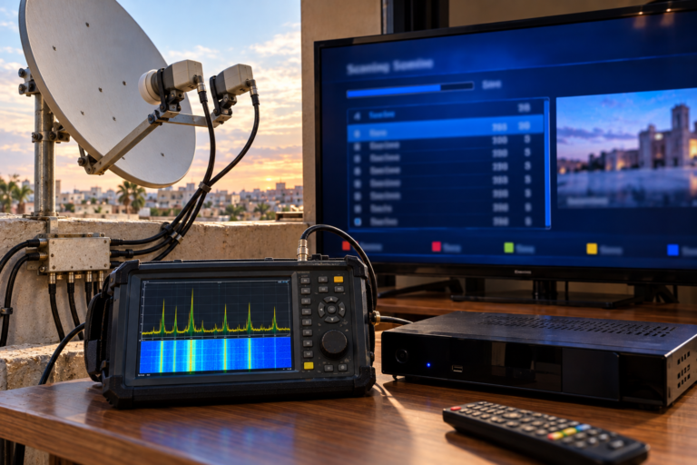
Step-by-Step: Diagnose Hot Bird H/V Signal Problems
Step 1: Confirm the Installed Distribution Type
Determine whether the receiver is connected directly to a universal LNB, through a DiSEqC switch, through a Quattro/multiswitch arrangement, or through SCR/dCSS equipment.
Record the existing settings before making changes.
Step 2: Choose Verified H and V Reference Carriers
Select current Hot Bird transponders on both polarizations.
Where practical, include low-band and high-band carriers so that polarization faults can be separated from band-switching faults.
Do not rely on outdated transponder entries or assume that a channel name confirms its current frequency.
Step 3: Check Lock Status and Quality
Record whether each carrier locks and, where available, measure MER, C/N, and relevant error performance.
A receiver’s signal-strength percentage is not a standardized measure of usable digital reception.
Document the actual modulation and coding parameters when comparing carrier margins.
Step 4: Identify the Failure Group
Check whether the problem affects all H carriers, all V carriers, only one frequency band, or isolated transponders.
A failure grouped by polarization suggests a different investigation from isolated weak frequencies across both polarizations.
Step 5: Verify Switching Commands and Voltage Delivery
For a conventional universal LNB, confirm the receiver’s polarization and band-selection configuration.
Qualified technicians can use appropriate satellite test equipment to inspect control voltage and tone behavior at suitable points in the system.
Do not assume that a voltage reading with no connected load proves correct operation during reception.
Step 6: Inspect the Physical RF Path
Check connectors, cable condition, switching hardware, and any weather-exposed joints.
Compare against a known-good equivalent path when the installation permits it.
Make physical connection changes only after disconnecting the relevant equipment from power.
Step 7: Evaluate LNB Skew and Alignment Separately
If both polarization states are available but quality remains unequal, inspect feed rotation and antenna alignment using representative carriers.
Make controlled adjustments and record the effect on MER or another suitable quality measurement.
Avoid optimizing one transponder at the expense of several others.
Step 8: Confirm the Diagnosis Before Replacing Hardware
A replacement LNB is justified when repeatable measurements or controlled substitution indicate a hardware problem.
If the fault follows a particular cable, switch, receiver, or distribution input, replacing the LNB may accomplish nothing.
Identify the installation → Verify current H/V carriers → Check lock and quality → Separate polarization from band failures → Test control signals and RF paths → Evaluate skew → Replace only the confirmed faulty component.
This approach is more reliable than rotating the LNB or changing receiver settings at random.
Reality Check: H/V Signal Differences Do Not Always Mean Switching Failure
A missing polarization group can indicate incorrect LNB control, voltage delivery, or distribution routing. But lower quality on several horizontal or vertical transponders does not necessarily establish an electrical fault.
Different transponders can have different received power levels, transmission requirements, and available link margins.
Skew errors and cross-polarization interference may also affect certain carriers without eliminating an entire polarization.
Do not diagnose the LNB from one H and one V transponder. Verify the failure pattern across several carriers and, where possible, both frequency bands.
Final Verdict
When Hot Bird 13°E signal changes between H and V, first determine whether the installation is failing to select a polarization or simply delivering different reception quality on individual carriers.
In a conventional universal-LNB system, nominal 13V and 18V states control vertical and horizontal polarization. Faulty voltage delivery, incorrect receiver settings, cable resistance, or defective LNB switching can prevent reliable selection.
When both polarizations remain accessible, investigate skew, cross-polarization isolation, transponder margin, antenna alignment, and frequency-dependent impairments.
For Quattro, multiswitch, and SCR/dCSS systems, use diagnostics appropriate to their distribution architecture.
The most effective repair is the one supported by a repeatable fault pattern and actual measurements, not simply the first component that seems related to polarization.
Frequently Asked Questions
Why do Hot Bird horizontal channels work but vertical channels fail?
Possible causes include incorrect 13V polarization selection, LNB switching faults, receiver configuration errors, or distribution problems. Check verified H and V carriers across both frequency bands before drawing a conclusion.
What voltage selects H and V on a universal LNB?
Conventional universal LNBs typically use a nominal 13V state for vertical polarization and 18V for horizontal polarization. Actual switching tolerances depend on the equipment.
Can a damaged coaxial cable affect only horizontal channels?
Yes. Excessive DC resistance or unreliable connections can interfere with the voltage state required for horizontal selection. Other cable faults can cause frequency-dependent RF problems. Testing is needed to distinguish these effects.
Does changing LNB skew improve H and V signal quality?
Correct skew can improve polarization isolation and reduce susceptibility to unwanted orthogonal-polarization energy. However, it does not repair a failed voltage-switching circuit.
Why is one Hot Bird polarization weaker even though both work?
Unequal carrier margins, feed alignment, interference, antenna performance, or equipment characteristics may contribute. Compare several verified transponders rather than assuming all H and V carriers should produce identical readings.
Do Unicable systems use 13V and 18V in the same way?
No. SCR and dCSS installations use compatible control commands and assigned user bands for signal selection. Their receiver-side control procedures differ from direct conventional universal-LNB polarization switching.
Should I replace my LNB if one polarization stops working?
Only after checking receiver settings, voltage delivery, cable condition, and the relevant distribution path. A controlled test with compatible known-good hardware can help confirm an actual LNB fault.