Why Astra Reception Changes Near a Footprint Edge
A satellite footprint map appears to draw a clear boundary between coverage and no coverage. But real reception does not stop at a sharp line. Near the edge of an Astra beam, one installation may receive a transponder reliably while another struggles to maintain a lock. Sometimes even a relatively small change in location or antenna performance can produce a noticeably different result.
The reason is not that the satellite suddenly stops transmitting beyond a mapped boundary. Satellite beams have gradual power distributions, and fringe reception operates with less available signal margin. When the received carrier approaches the demodulator’s operating threshold, relatively small changes in weather, antenna gain, alignment or interference can determine whether the television picture remains stable or disappears.
Astra reception near a footprint edge depends on the local power delivered by the specific satellite beam, the receiving antenna’s performance and the margin required by each transponder. Coverage contours are estimates of expected signal levels, not guaranteed reception boundaries. Fringe installations can work outside commonly illustrated coverage regions, but reliability may be highly sensitive to equipment performance and weather conditions.
What a Satellite Footprint Really Represents
A satellite footprint describes the geographic distribution of a satellite antenna beam over the Earth’s surface.
Communication satellites do not radiate equal power in every direction. Their transmitting antennas are designed to concentrate energy over selected coverage regions.
Within those regions, the expected received power varies according to the beam pattern.
Satellite operators often publish footprint maps to illustrate where particular beams are intended to provide service.
These maps are useful for planning, but they do not show every factor that determines reception at an individual installation.
Astra 19.2E is an orbital position used by multiple satellite payloads and beams. It should not be treated as one uniform coverage area.
A location may receive one Astra beam strongly while another beam from the same orbital position delivers substantially less power.
That distinction becomes especially important near the outer regions of a coverage footprint.
When evaluating reception, the relevant question is not simply whether a location appears inside an Astra map. It is whether the specific beam carrying the required transponder provides enough received power for the intended receiving system.
Understanding EIRP Contours
Satellite footprint maps commonly use Effective Isotropic Radiated Power (EIRP) contours.
EIRP combines transmitter power and transmitting antenna gain, expressed relative to an ideal isotropic radiator.
For satellite systems, EIRP is commonly expressed in dBW.
A contour connects locations where the modeled EIRP is approximately equal.
For example, a map may show a sequence of contours representing progressively lower expected power farther from the main coverage region.
These contours describe the transmitted beam’s geographic power distribution.
They do not directly measure the modulation quality available at an individual receiver.
The actual receiving system must still account for propagation losses, antenna gain, noise performance and transmission requirements.
A coverage map may also include suggested dish diameters, but those recommendations depend on assumptions about the link budget and desired service availability.
Different planning assumptions can produce different dish-size recommendations for the same EIRP contour.
Important distinction: EIRP is a transmitted-power quantity. Receiver signal quality, MER and carrier-to-noise ratio are different quantities measured or estimated at the receiving end. They should not be treated as interchangeable.
Why a Footprint Edge Is Not a Hard Boundary
A footprint map can create the impression that reception should work inside a line and stop immediately outside it.
Real antenna radiation patterns do not normally behave that way.
The transmitted power generally changes continuously across the beam pattern.
There may be steep gradients, local variations and sidelobes, but a mapped contour is not a physical wall.
Outside a commonly illustrated coverage contour, some usable signal may still be present.
Whether that signal can be decoded depends on the receiving antenna and the complete link budget.
This explains why fringe reception is sometimes possible beyond the main intended service area.
However, reception outside a published contour should not be assumed reliable simply because another installation has succeeded.
Small differences in antenna gain, equipment noise, alignment and local conditions can make a large practical difference when the available margin is limited.
Coverage maps also have finite resolution and represent modeled or characterized beam performance rather than an exact prediction for every rooftop.
How Received Power Changes Across a Beam
The main region of a satellite beam is generally designed to provide useful coverage over a specified geographic area.
As a receiving location moves away from the strongest part of the beam, the expected EIRP may decrease.
The rate of decrease depends on the transmitting antenna pattern.
It is not necessarily uniform in every direction.
Some parts of a beam may have relatively gradual power changes, while other regions have steeper gradients.
As a result, moving a modest geographic distance can sometimes change the expected received power noticeably, particularly near a steep contour region.
However, it would be incorrect to claim that every small movement near every footprint edge produces a large signal difference.
The actual result depends on the local beam gradient and other reception conditions.
When comparing two installations, the difference in EIRP should therefore be evaluated using the relevant beam information rather than assumed from distance alone.
Why Fringe Reception Has Less Signal Margin
The defining challenge of fringe reception is often limited link margin.
A digital satellite receiver requires a sufficiently clean signal to demodulate and decode a carrier reliably.
The required operating conditions depend on the transmission standard, modulation, forward error correction and receiver implementation.
Link margin describes how far the available reception conditions remain above the minimum required operating condition.
In a strong coverage area, a correctly installed receiving system may have enough margin to tolerate moderate additional attenuation or impairment.
Near the edge of a weaker beam, the same receiving system may operate much closer to the required threshold.
That makes the result more sensitive to changes in the propagation path and equipment performance.
Installation A has an estimated 4 dB of margin above the required decoding condition.
Installation B has only 0.8 dB of margin.
If both experience an additional 1.5 dB degradation, Installation A retains approximately 2.5 dB of margin, while Installation B falls below its required condition.
These figures are illustrative and are not measured Astra 19.2E reception values or universal DVB-S2 thresholds.
This threshold behavior explains why a fringe installation may appear stable under favorable conditions but become unreliable after a relatively small deterioration.
The problem is not necessarily that the signal has disappeared completely.
It may simply have fallen below the level of quality required for successful decoding.
Rain and Atmospheric Effects Near the Coverage Edge
Ku-band satellite reception is affected by atmospheric attenuation, particularly during rain.
Rain droplets absorb and scatter part of the radio-frequency energy traveling through the atmosphere.
This reduces the signal available at the receiving antenna.
In a strong coverage region, the receiving system may have sufficient clear-sky margin to tolerate some additional attenuation.
At a fringe location, the same attenuation may be enough to interrupt reception.
However, rain fade is not determined by geographic distance from a footprint edge alone.
It depends on local rainfall intensity, propagation geometry, operating frequency and other environmental conditions.
Low elevation angles can increase the atmospheric path length and may make some receiving locations more vulnerable to attenuation.
Clouds, atmospheric gases and other propagation effects can also contribute to the total link loss.
For dependable fringe reception, the antenna system should be evaluated against the expected weather conditions and required service availability.
A system that works during clear weather is not necessarily designed for high availability throughout the year.
For a detailed explanation of carrier-specific weather behavior, read Why One Astra Transponder Breaks Up in the Rain.
Why Different Astra Beams Behave Differently
Not every Astra 19.2E transponder has the same geographic coverage characteristics.
Different satellite beams can illuminate different regions with different expected power levels.
Consequently, a fringe receiving location may have very different margins on different carriers.
One transponder may be carried by a beam that provides relatively strong local coverage.
Another may use a beam whose expected EIRP is substantially lower at the same location.
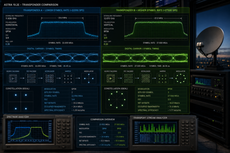
The two carriers may also use different modulation and coding configurations.
That means their required decoding conditions may differ even if their received power levels are similar.
This is why evaluating fringe reception using only one convenient transponder can be misleading.
A successful lock on one carrier does not establish that all desired services will be available.
For a technical explanation of these differences, see Why Astra Signal Quality Changes Across Frequencies.
Dish Gain, Alignment and Pointing Accuracy
Antenna gain becomes particularly important when the received satellite power is limited.
A larger reflector generally provides more gain than a smaller reflector operating at the same frequency with comparable efficiency.
That additional gain can improve the available carrier-to-noise performance when insufficient received signal is the limiting factor.
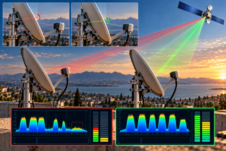
However, fringe reception also requires accurate antenna pointing.
Parabolic antennas have directional radiation patterns, and the main beam becomes narrower as antenna diameter increases.
A larger dish can therefore provide more gain while also demanding greater pointing accuracy and mechanical stability.
Even a small pointing error may reduce the available gain.
When reception margin is already limited, that reduction can be significant.
Other antenna-related factors include:
- Reflector surface accuracy
- Feed position and illumination
- LNB skew
- Mounting stability
- Obstructions in the satellite line of sight
- Wind-induced movement
A larger dish is useful only when it is properly installed and aligned.
For a separate discussion of diameter selection, read Why a 60cm Dish Works for Astra in Some Countries.
LNB Noise, Receiver Thresholds and Distribution Losses
Fringe reception is not determined by the reflector alone.
The complete receiving system influences the available margin.
The LNB contributes noise and must provide suitable gain, stability and linearity.
Its performance should be evaluated as part of the overall system rather than by one advertised specification.
A receiver’s demodulator also has operating limits that depend on the selected transmission mode.
Two receivers connected to the same antenna system may therefore behave differently near the decoding threshold.
One may maintain a usable transport stream under conditions where another begins reporting errors or loses lock.
Distribution losses can also matter.
Long coaxial runs, damaged connectors and poorly designed distribution equipment may reduce signal level or introduce impairments.
However, ordinary post-LNB cable attenuation does not automatically reduce carrier-to-noise ratio by the same number of decibels.
Its effect depends on the available LNB gain, downstream noise contribution, receiver input range and other system conditions.
For this reason, the objective should be to measure the complete signal path rather than assume every weak fringe installation needs a higher-gain LNB.
Why Nearby Installations Can Have Different Results
Two homes near the same coverage contour may receive the same Astra beam with different levels of reliability.
There are two broad reasons.
First, the expected satellite power may vary between the locations if they lie along a significant beam gradient.
Second, their receiving installations may have different performance.
For example, one home may use a carefully aligned reflector with suitable gain and a clear line of sight.
The other may have a slightly distorted dish, an obstructed view, poor skew adjustment or damaged coaxial connections.
Even if the expected EIRP is nearly identical, the second installation may have substantially less usable margin.
This is particularly noticeable near the decoding threshold.
One system continues operating while the other experiences freezing or intermittent lock loss.
That difference does not necessarily prove that the footprint map is inaccurate.
It may simply reflect the fact that the two installations have different link budgets.
How to Evaluate a Fringe Reception Site
Fringe reception should be evaluated using a repeatable measurement process.
Receiver quality percentages alone are not sufficient because manufacturers do not use one standardized percentage scale.
Step 1: Identify the Required Transponders
Determine which Astra 19.2E services are actually needed.
Record their current frequencies, polarizations, symbol rates and transmission modes using reliable, up-to-date information.
Step 2: Identify the Relevant Satellite Beams
Consult current satellite operator coverage information where available.
Do not assume every transponder at the orbital position uses the same beam.
Step 3: Examine the Receiving Location
Check the expected coverage, satellite elevation and physical line of sight.
Identify buildings, trees or terrain that could obstruct the antenna.
Step 4: Verify the Antenna Installation
Confirm that the reflector is mechanically stable and accurately pointed.
Check feed positioning and LNB polarization alignment.
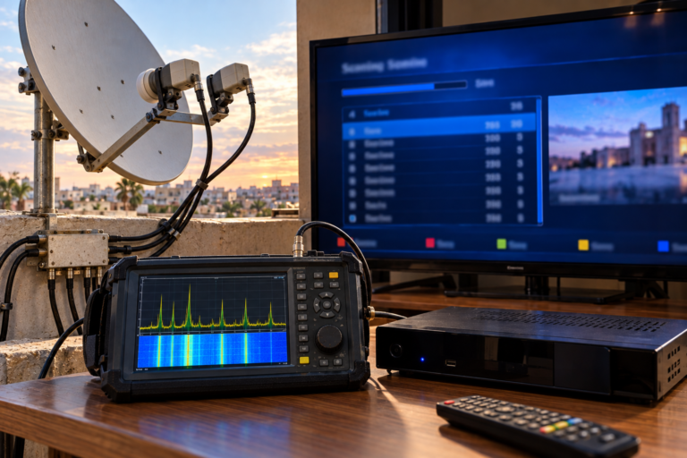
Step 5: Measure Representative Carriers
Use suitable satellite measurement equipment to record signal level, MER, C/N and error performance where available.
Include carriers from the different beams and transmission modes relevant to the installation.
Step 6: Evaluate Available Margin
Compare the measured reception conditions with the requirements of the relevant modulation and coding modes.
Do not apply one universal MER threshold to every DVB-S2 carrier.
Step 7: Account for Weather Availability
Consider whether the installation needs to remain operational during typical rain conditions or meet a higher availability target.
Clear-sky reception alone does not establish year-round reliability.
Step 8: Test the Distribution Path
Check cables, connectors and switching equipment for faults that could reduce the usable margin.
Power off connected equipment before disconnecting satellite coaxial cables.
Step 9: Compare Improvements Systematically
If changes are needed, adjust one factor at a time and record the measurement results.
This helps establish whether alignment, cabling, LNB performance or antenna gain is responsible for the improvement.
Fringe Reception Diagnostic Patterns
| Observed Pattern | Possible Explanation | Recommended Investigation |
|---|---|---|
| One beam works while another is weak | Different local beam EIRP or reception requirements | Compare beam coverage and carrier margins |
| Channels work in clear weather but fail during rain | Insufficient fade margin | Evaluate clear-sky margin and weather availability |
| Small alignment changes affect reception noticeably | Limited margin or narrow antenna beamwidth | Optimize pointing using suitable measurements |
| Nearby homes have different reception results | Different installation performance or local beam conditions | Compare antennas, obstructions and measured carrier quality |
| One receiver locks while another fails | Different tuner performance or signal paths | Compare compatible receivers on the same known-good path |
| Signal level is adequate but MER is poor | Noise, interference or distortion | Investigate modulation quality and RF impairments |
| A larger dish improves several weak carriers | Additional antenna gain increases available margin | Verify results across all required transponders |
These patterns help identify likely causes, but none should be treated as definitive proof without appropriate measurements.
When a Larger Dish Can Help
A larger dish can be useful when insufficient receiving antenna gain is the main limitation.
For antennas operating at the same frequency with comparable efficiency, the theoretical gain difference is approximately:
Gain difference (dB) ≈ 20 log₁₀(D₂ / D₁)
Where D₁ and D₂ are the two reflector diameters.
This relationship assumes comparable aperture efficiency and operating frequency. Actual performance depends on antenna design and installation quality.
Additional antenna gain can improve the link budget and provide more margin against attenuation.
However, it is important to establish that antenna gain is actually the limiting factor.
If the installation suffers from severe interference, incorrect LNB switching, damaged connectors or blocked line of sight, increasing reflector diameter may not resolve the problem.
A larger dish also requires a suitable mount and accurate pointing.
In difficult fringe locations, professional site evaluation is often more useful than repeatedly replacing equipment based on receiver percentage readings.
Reality Check
A satellite footprint edge is not a guaranteed boundary between working and non-working reception.
Footprint maps represent expected beam power distributions, commonly expressed using EIRP contours.
Actual reception depends on the complete link budget, including antenna gain, system noise, modulation requirements, local conditions and weather margin.
Fringe reception may be possible outside a commonly illustrated contour, but it can be less reliable because the available margin is limited.
Likewise, two nearby installations may behave differently because of equipment performance and line-of-sight conditions, even when their expected satellite power is similar.
The most useful question is not whether a location is technically inside or outside a map boundary. It is whether the receiving system has enough margin to meet the required service availability.
Final Verdict
Astra reception changes near a footprint edge because the available satellite signal power and decoding margin can become limited, making the receiving system more sensitive to additional losses and impairments.
Satellite beam coverage does not end at a perfectly defined line. EIRP varies across the radiation pattern, and the practical reception result depends on the complete receiving installation.
Near weaker coverage regions, accurate dish alignment, suitable antenna gain, LNB performance and proper cabling become increasingly important.
Rain attenuation can further reduce the available margin, causing a transponder that works in clear weather to fail under less favorable conditions.
Different Astra beams and transmission modes can also produce different results at the same receiving location.
The correct approach is to identify the required transponders, examine the relevant beam coverage, measure reception quality and determine whether the available margin meets the intended reliability target.
Fringe reception is not simply a question of whether the satellite can be detected. It is a question of whether the complete receiving system can decode the required services consistently under real operating conditions.
Frequently Asked Questions
| Question | Answer |
|---|---|
| What is the footprint edge of a satellite? | It is a region near the outer part of a satellite beam’s mapped coverage, often represented by EIRP contours. It is not necessarily a hard reception boundary. |
| Can Astra 19.2E be received outside its published footprint? | Sometimes. Usable signal may extend beyond a published contour, but reliable reception depends on the receiving system and available margin. |
| Why does Astra reception become unstable near the coverage edge? | Lower available signal power can reduce decoding margin, making the system more sensitive to rain, pointing errors and other impairments. |
| Do all Astra 19.2E transponders have the same footprint? | No. Different satellites and beams at the orbital position can have different coverage characteristics. |
| Why can nearby homes receive Astra differently? | They may have different antenna performance, alignment, obstructions or local beam conditions. |
| Does rain affect fringe reception more? | Rain attenuation affects satellite links generally, but a fringe installation with less margin may lose reception sooner. |
| Will a larger dish improve fringe reception? | It can help when insufficient antenna gain is the main limitation. It will not automatically fix interference, configuration faults or obstructions. |
| Are satellite footprint maps completely accurate? | They are useful planning representations, but they cannot predict every local installation condition or guarantee reception. |
| What measurements are useful for fringe reception? | Signal level, MER, C/N, error performance and carrier-lock status are useful when interpreted with the transmission mode and measurement conditions. |
| How can I make Astra fringe reception more reliable? | Verify the correct beam and transponders, optimize antenna alignment, inspect the signal path and evaluate whether additional antenna gain or fade margin is needed. |