Why Satellite TV Pixelates Instead of Going Snowy
Estimated Reading Time: 12 minutes
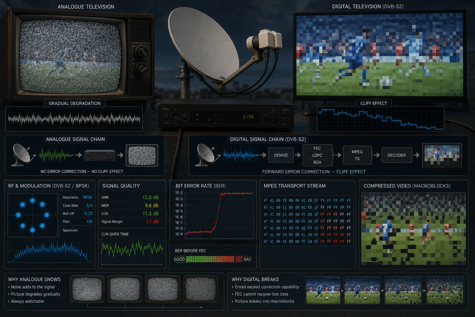
Older analogue television pictures usually became noisier as reception weakened. Fine dots appeared across the screen, colours became unstable, and the picture gradually disappeared beneath visible snow. Digital satellite television behaves very differently. Its picture can remain almost perfect and then suddenly break into squares, freeze, lose audio, or disappear completely.
This happens because a digital receiver does not reproduce every small variation arriving from the satellite as visible picture noise. It reconstructs compressed video from packets of binary data. As long as modulation decisions and error-correction systems recover those packets successfully, the picture remains clean. When too much data becomes damaged or missing, the decoder can no longer rebuild complete frames, producing pixelation rather than analogue snow.
Analogue reception displays signal impairment directly as picture noise. Digital satellite reception converts the carrier into symbols, bits, transport stream packets, and compressed video frames. Errors can remain hidden until Forward Error Correction and decoder concealment reach their limits. The result is a rapid transition from a clean picture to macroblocking, freezing, audio interruption, or complete signal loss.
- Why Analogue Television Went Snowy
- Why Digital Satellite Television Behaves Differently
- How a Satellite Picture Becomes Digital Data
- What an MPEG Transport Stream Does
- Why Missing Data Appears as Squares
- What Macroblocks and Coding Blocks Are
- Why Compressed Frames Depend on One Another
- How Packet Loss Spreads Across the Picture
- Why Forward Error Correction Hides Problems
- BER and the Beginning of Pixelation
- The Digital Cliff Effect
- Why the Picture Freezes Before It Disappears
- Why Audio and Video Fail Differently
- Why Fast Movement Makes Pixelation More Visible
- Common Causes of Satellite Pixelation
- How to Troubleshoot Pixelation Correctly
- Reality Check
- Final Verdict
- FAQ
Why Analogue Television Went Snowy
Analogue television carried continuously varying electrical information representing picture brightness, colour, synchronisation, and sound. When reception weakened, noise became a larger part of the received waveform.
The television reproduced some of that unwanted electrical noise directly. Random variations appeared as bright and dark dots across the screen, creating the familiar snowy picture.
The deterioration was usually gradual. A small reduction in signal quality produced a slightly noisy image. A larger reduction created heavier snow, unstable synchronisation, colour loss, rolling, or complete picture failure.
The viewer could often see reception becoming worse long before the programme disappeared. The amount of visible noise acted as a rough indication of the remaining analogue signal quality.
Why Digital Satellite Television Behaves Differently
Digital satellite television does not transmit a continuously varying copy of every displayed pixel. The programme is converted into compressed digital data before transmission.
The receiver must first lock onto the RF carrier, recover symbol timing, identify modulation symbols, reconstruct bits, apply error correction, recover the transport stream, separate the selected programme, and decode its video and audio.
At each stage, the receiver makes decisions. A received symbol is interpreted as one of several valid symbol states. The resulting bits are checked and corrected. Valid packets are passed towards the video decoder, while unusable information may be discarded or concealed.
Minor RF noise is therefore not automatically drawn on the screen. If the receiver still identifies the symbols correctly, the reconstructed data is identical to the original transmitted data and the picture remains clean.
How a Satellite Picture Becomes Digital Data
Before transmission, the broadcaster compresses the programme using a video codec such as MPEG-2, H.264/AVC, or HEVC. Compression removes spatial and temporal redundancy so the channel requires much less satellite capacity than uncompressed video.
The compressed video, audio, subtitles, timing information, and service data are organised into elementary streams. These streams are packetised and combined into a transport stream containing one or more television and radio services.
The transport data then passes through channel coding, interleaving, framing, and modulation before it is transmitted from the satellite.
At the receiving end, the process is reversed. The receiver must recover the digital transport stream before it can reconstruct the programme picture.
MPEG transport streams are specifically designed for environments where transmission errors may occur, allowing receivers to identify packet boundaries, select individual services, and maintain timing across a multiplex. :contentReference[oaicite:0]{index=0}
What an MPEG Transport Stream Does
A satellite transponder normally carries a continuous MPEG transport stream divided into fixed-length packets. Each packet contains a header and a portion of programme data or service information.
Packet identifiers tell the receiver which packets belong to the selected video, audio, subtitles, programme tables, or other components.
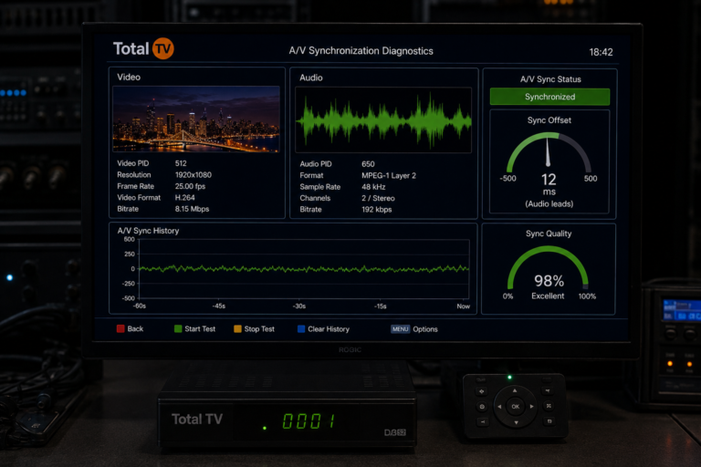
Continuity information helps the receiver detect when packets have been lost, repeated, or received out of sequence. Timing references keep audio, video, and the receiver clock synchronised.
When reception is healthy, the receiver obtains the required packets in the correct order and passes the compressed programme to the decoder.
When RF errors damage packet headers or payloads, the receiver may be unable to use the affected information. What happens next depends on which packets were damaged and how important they were to the compressed picture.
Why Missing Data Appears as Squares
Compressed video is processed in rectangular regions rather than as one indivisible full-screen image. Depending on the codec, these regions may be described using macroblocks, coding tree units, transform blocks, prediction blocks, or related structures.
Each region contains information needed to reconstruct part of the frame. That information can include brightness and colour data, prediction instructions, motion vectors, transform coefficients, and references to earlier or later frames.
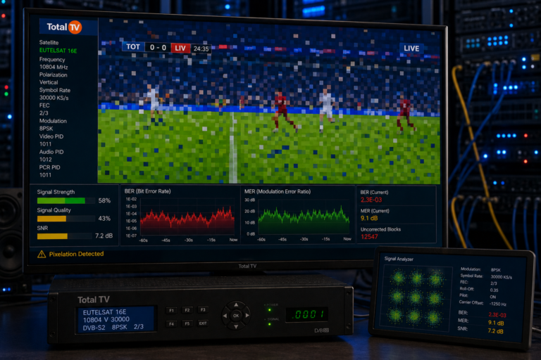
If part of the compressed data is lost, the decoder may be unable to reconstruct one or more regions correctly. The damaged area then appears as a block, a cluster of squares, a frozen patch, or a region borrowed from an earlier frame.
The squares are not pieces of the satellite signal itself. They are visible boundaries created by the way the digital video codec divides, predicts, and reconstructs the picture.
What Macroblocks and Coding Blocks Are
The word macroblocking is commonly used to describe the large square patterns visible during digital television failure.
In older MPEG video systems, a macroblock represented a defined rectangular group of picture samples. Modern codecs use more flexible coding structures, but viewers still use macroblocking as a general description for block-shaped corruption.
Block boundaries can become visible when compressed information is missing or when the decoder repeats incomplete prediction data.
Not every square on a television screen proves that satellite packets were lost. Excessive video compression can also reveal block boundaries even when RF reception is perfect.
Reception-related macroblocking is more likely to appear suddenly, change unpredictably, occur with audio interruptions, or affect multiple channels on the same transponder at the same time.
| Visible Symptom | Possible Digital Cause | Likely Receiver Behaviour |
|---|---|---|
| Small random blocks | A limited number of damaged packets or corrected data gaps | The decoder conceals or replaces small missing regions |
| Large frozen squares | Important prediction or frame data is missing | Parts of an older frame remain visible |
| Whole picture freezes | No complete decodable frame is available | The receiver holds the last valid frame |
| Audio clicks or briefly mutes | Damaged or missing audio packets | The decoder conceals, repeats, or mutes the affected samples |
| Picture disappears completely | Transport stream, demodulator, or carrier lock is lost | The receiver displays no signal, no service, or a blank screen |
| Blocks appear only during complex scenes | Insufficient encoding bitrate or heavy compression | RF readings may remain completely stable |
Why Compressed Frames Depend on One Another
Digital video compression does not normally transmit every frame as a complete independent picture.
Some frames contain a more complete representation of the image and can serve as reference points. Other frames store mainly the changes that occurred relative to previous or future reference pictures.
An intra-coded frame can be decoded without depending heavily on another picture. Predicted frames use motion estimation and reference data to avoid retransmitting unchanged parts of the scene.
This makes video compression efficient, but it also means that one damaged reference frame can affect several later frames.
If a packet containing important reference information is lost, the decoder may continue using corrupted or incomplete data until a new usable reference picture arrives.
How Packet Loss Spreads Across the Picture
The visible effect of one damaged packet depends on where that packet belongs inside the compressed video stream.
Loss affecting a small, independently decodable region may create only a brief block. Damage to motion vectors or reference-picture information can produce a larger area of corruption that persists across multiple frames.
The decoder may attempt error concealment by copying pixels from nearby areas, repeating information from the preceding frame, or estimating motion from available data.
These methods can make minor damage less noticeable, but they cannot recreate information the receiver never received.
As more packets become corrupted, concealment becomes less effective. The screen then develops larger blocks, frozen sections, colour errors, and repeated frames.
Why Forward Error Correction Hides Problems
DVB satellite systems transmit additional coding information that allows the receiver to detect and repair many errors without requesting retransmission.
This process is called Forward Error Correction. DVB-S2 uses powerful channel coding, including LDPC and BCH protection, to recover data affected by noise and other transmission impairments.
As reception weakens, the number of raw bit errors can rise while the viewer continues seeing a flawless picture. The correction system is repairing those errors before they reach the transport stream.
This creates a hidden warning period. The installation may already be losing signal margin even though no visible fault has appeared.
Once the incoming damage exceeds the correction capacity, uncorrected errors begin reaching the transport stream. Pixelation may then appear very suddenly.
BER and the Beginning of Pixelation
BER, or Bit Error Rate, measures how many received bits are incorrect compared with the transmitted data.
Pre-FEC BER describes errors before correction. Post-FEC BER describes errors remaining after the correction process.
A rising pre-FEC error rate does not always create immediate visible damage because the receiver can still repair the data.
Post-FEC errors are more serious. They indicate that damaged information is escaping the correction system and entering later decoding stages.
At first, only occasional packets may be affected, producing brief blocks or audio clicks. As BER becomes worse, more packets are damaged and the decoder loses complete frames or transport synchronisation.
The Digital Cliff Effect
Digital reception often changes from reliable to unusable across a narrow range of signal conditions.
Above the decoder threshold, error correction recovers enough information to maintain an apparently perfect programme. Slightly below that threshold, uncorrected errors rise rapidly and reception collapses.
This behaviour is known as the digital cliff. It explains why the picture can change from clear to heavily pixelated after only a small reduction in signal quality.
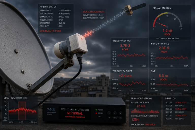
A slightly misaligned dish may therefore work perfectly during dry weather but fail quickly when rain reduces the carrier level.
The clear picture did not prove that the installation had strong margin. It proved only that reception remained above the minimum threshold at that moment.
Why the Picture Freezes Before It Disappears
When new compressed frames cannot be decoded, many receivers continue displaying the most recent valid frame.
Holding the last good picture is less visually disruptive than immediately producing a blank screen. It also gives the receiver time to recover from a brief interruption.
If some new data remains usable, parts of the frame may update while other regions stay frozen. This produces a patchwork image containing information from different moments.
If the receiver recovers quickly, the picture resumes after a short freeze. If errors continue, the transport stream or demodulator may lose synchronisation completely.
The receiver then removes the frozen frame and displays a blank screen, a no-signal message, or a service error.
Why Audio and Video Fail Differently
Audio and video are compressed separately and carried in different transport stream packets. Damage does not always affect both components at exactly the same moment.
A missing video packet may corrupt part of a predicted frame while the audio stream remains intact. The viewer sees blocks but continues hearing normal sound.
In another case, an audio packet may be damaged while the picture remains stable. The audio decoder may mute briefly, repeat a small section, or create a click.
Audio normally requires much less data than video and may use independent concealment techniques. This can allow sound to continue after the picture freezes.
Once reception becomes severe enough to disrupt the complete transport stream, both audio and video fail.
Why Fast Movement Makes Pixelation More Visible
Fast-moving sport, water, smoke, crowds, flashing lights, and rapid camera movement are difficult to compress because large parts of the picture change between frames.
These scenes require more prediction data and more coded detail than a static studio shot.
When packets are lost during a complex sequence, the decoder has fewer unchanged regions it can conceal successfully. Motion errors and missing reference information become highly visible.
Fast movement can therefore make an RF fault look more dramatic, even if the measured satellite condition has not changed.
However, blocks that appear only during movement can also be caused by insufficient broadcast bitrate rather than reception failure. Signal quality, BER, audio behaviour, and other channels on the transponder should be checked before blaming the dish.
Common Causes of Satellite Pixelation
Dish misalignment is one of the most common causes. A small azimuth or elevation error reduces the wanted carrier and leaves less margin above the decoding threshold.
Incorrect LNB skew can introduce interference from the opposite polarization. The strength reading may remain high while MER falls and BER rises.
Rain fade weakens Ku-band satellite signals through absorption and scattering. Light rain may produce no visible effect on a healthy installation, while a marginal system begins pixelating quickly.
Wind can move an inadequately secured dish. A bent reflector, damaged LNB holder, or unstable mounting pole can also prevent consistent focus.
Corroded connectors, moisture ingress, poor coaxial cable, unsuitable splitters, defective switches, and excessive distribution loss can damage the signal between the LNB and receiver.
LNB oscillator instability, phase noise, electrical interference, receiver overheating, and failing power supplies can create similar symptoms.
| When Pixelation Appears | More Likely Cause | First Checks |
|---|---|---|
| During rain | Insufficient fade margin | Dish size, alignment, skew, cable loss, and weatherproofing |
| During strong wind | Dish or mounting movement | Pole stability, bolts, reflector, and LNB bracket |
| On one complete transponder | Frequency-specific RF or transmission problem | BER, MER, polarization, interference, and transponder parameters |
| On high-band channels only | LNB switching or distribution fault | 22 kHz control, cable, switches, connectors, and LNB |
| After the receiver becomes hot | Receiver or power-supply instability | Ventilation, firmware, tuner temperature, and power supply |
| Only during detailed fast scenes | Possible compression limitation | Check RF measurements and compare other channels on the transponder |
| When the cable is touched | Loose or damaged connection | F-connectors, centre conductor, shielding, and cable damage |
How to Troubleshoot Pixelation Correctly
Begin by identifying whether the problem affects one channel, every channel on one transponder, one polarization, one frequency band, or the complete satellite package.
If several channels sharing the same transponder pixelate together, the problem is likely to be within the RF reception path or the transmitted multiplex rather than the individual video codec.
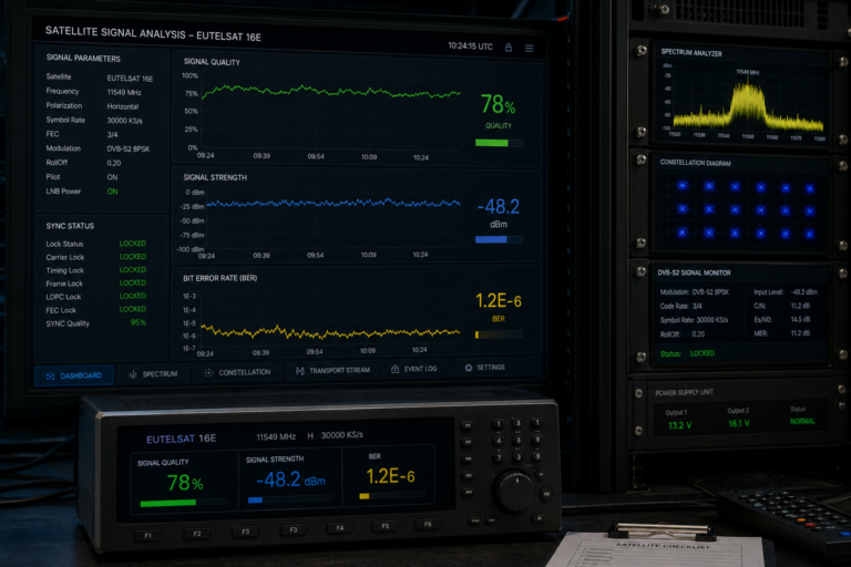
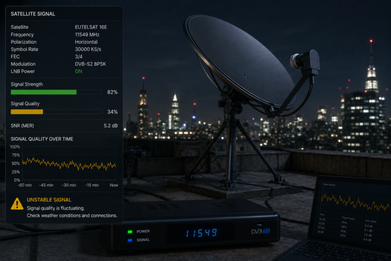
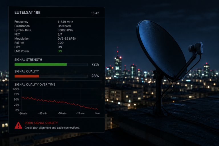
Observe signal quality, BER, MER, and lock stability. Do not rely only on the strength bar, because strong RF power can coexist with serious noise, interference, or polarization errors.
Check whether the fault follows rain, wind, temperature, or movement of the cable. Environmental patterns can identify insufficient margin, mechanical instability, moisture, or failing connections.
Fine-tune dish azimuth, elevation, and LNB skew using a weak but important transponder. Test several frequencies across both polarizations and frequency bands.
Inspect outdoor connectors for corrosion and water. Confirm that the centre conductor is correctly seated and that no shielding strands touch it.
Remove unnecessary adapters, splitters, and extensions during testing. If possible, connect the receiver through a known-good cable directly to the LNB.
When the receiver shows increasing errors before the picture breaks into blocks, the underlying process can be understood through what BER really means on a satellite receiver. BER reveals how quickly the incoming data is becoming too damaged for the correction system to recover.
Not every blocky picture is caused by weak satellite reception. Broadcasters can create visible blocking by compressing a complex programme too aggressively or assigning too little bitrate.
Receiver software faults, failing hardware, overheating, damaged recordings, network-based delivery problems, or television processing can also produce freezing and blocks.
RF-related pixelation is more likely when BER rises, signal quality fluctuates, audio is interrupted, multiple channels on the same transponder fail together, or the fault changes with weather and dish movement.
Satellite television pixelates instead of going snowy because it is reconstructed from compressed digital packets rather than displayed as a continuously varying analogue waveform.
Noise and interference remain invisible while the receiver can identify the modulation symbols and repair damaged bits. When Forward Error Correction reaches its limit, missing transport stream data prevents the video decoder from reconstructing complete coding regions and predicted frames.
The result is macroblocking, frozen sections, repeated frames, audio interruption, and eventually complete loss of lock. The transition can be sudden because digital reception remains clean until it approaches the decoding threshold.
Reliable reception depends on more than signal strength. Accurate dish alignment, correct LNB skew, healthy MER, low BER, clean cables, stable equipment, and sufficient weather margin are what keep the digital picture intact.
| Question | Answer |
|---|---|
| Why does digital satellite television show squares? | Compressed video is reconstructed in rectangular coding regions. When packets are damaged or missing, the decoder cannot rebuild some regions correctly, making block boundaries visible. |
| Why does analogue television show snow instead? | Analogue receivers reproduce variations and noise in the incoming waveform directly, so weaker reception gradually appears as random bright and dark dots. |
| What is macroblocking? | Macroblocking is the common name for visible square or rectangular regions created when digital video compression or missing data prevents smooth picture reconstruction. |
| Why can the picture remain perfect before pixelation starts? | Forward Error Correction repairs many transmission errors before they reach the video decoder. Visible damage begins when the correction capacity is exceeded. |
| Why does the screen freeze? | The receiver may hold the last correctly decoded frame when it cannot reconstruct a new complete frame. |
| Why does sound sometimes continue after the picture freezes? | Audio and video use separate packets and decoders. The audio packets may remain usable even when important video information is missing. |
| Why does pixelation appear during rain? | Rain attenuates the satellite carrier, reducing reception margin and increasing the number of symbol and bit errors. |
| Can high signal strength still produce pixelation? | Yes. The received power may include noise or interference, while poor MER and rising BER make the wanted carrier difficult to decode. |
| Can incorrect LNB skew cause blocks? | Yes. Incorrect skew reduces polarization isolation and allows unwanted cross-polarized energy to interfere with the selected transponder. |
| Why is pixelation worse during football matches? | Fast movement and changing detail are harder to compress and conceal. Missing data becomes more visible during complex scenes, although insufficient broadcast bitrate can cause similar blocks. |
| Does every blocky image mean the dish is misaligned? | No. Excessive compression, receiver faults, overheating, damaged recordings, and distribution problems can also create block-shaped artefacts. |
| What should be checked first? | Check which channels and transponders are affected, then examine quality, BER, MER, weather patterns, dish alignment, LNB skew, cables, connectors, and receiver stability. |